Training & FAQs
Find a training in your area or browse our technical FAQs.

Your Go-To Source for the Latest Service Insights
Hoshizaki Tech Digest brings service insights, training event information, troubleshooting resources, and product updates directly to techs in the field. Click the button or scan the QR code to sign up.
Flaker & DCM FAQs
Hoshizaki flakers have a unique feature with the automatic periodic flush system. This feature has also been added to the latest DCM products. The purpose of the periodic flush is to clean the water system daily to provide better efficiency, reduce preventative maintenance, and give longer life to the auger bearings.
The basic periodic flush shuts down the refrigeration system for 20 minutes every 12 hours to allow the water system to drain. This draining action completely empties the water system to drain away impurities. The reservoir is then re-filled with clean fresh water. The flush is accomplished by using a mechanical flush timer and a gravity flow flush valve. A manual flush switch is also included to allow manual draining of the water system for service.
There are two models that do not use a mechanical timer. They are the F-300B and the F-500B series under-counter flakers. These models drain the complete water system each time the unit cycles down. This is considered an off cycle drain down and provides the same result as the timed flush.
It is important to remember the flush timer if you are diagnosing a problem on a unit that will not start. Rotating the cam wheel clockwise will advance the timer. This will allow the unit to start if it was off on a periodic flush. The timer motor runs continuously when the power switch is ON. There are no adjustments to the length of the flush time. The flush period however, can be adjusted to occur at a specific time each day. This can be done by rotating the cam wheel until the micro-switch opens. The unit will flush every 12 hours from that specific time.
In order for the gear motor and compressor to start, the reservoir must be full and both float switches must be in the up position (closed). A full reservoir indicates that the inlet water valve, dual float switch, and water control relay have operated. It also indicates that control voltage, (24 volts A/C) should be present. This can be checked across terminals 1 & 2 on the timer board. If control voltage is not present, check the 1 amp buss type fuse located on the front of the control box. This fuse protects the control circuit (transformer secondary). If the fuse is OK, check the control transformer primary for 120 volts.
If you find control voltage present at terminals 1 & 2, check for voltage at terminal 8. This will either be control or line voltage depending on the model. Check the unit wiring diagram to determine what voltage should be present. Voltage here indicates that the timer board has sequenced properly to energize the gear motor circuit and is OK to this point. If voltage is present at terminal 8 and the gear motor has not started, check the gear motor relay circuit. Remember there is a built in time delay. This will be approx. 1~2 minutes depending on the model of the flaker. If it starts, give it time to cycle up completely. Turning off the power restarts the timer count which delays the cycle.
If no voltage is present at terminal 8, a jumper can be used to distinguish between a bad board or an electrical circuit problem. At this time, install a jumper across terminals 3 & 4 on the control timer board. Do not confuse terminals 3 & 4 with the line voltage compressor relay connections marked 3 & 4 (black relay) located on the timer board. If the unit sequences properly with this jumper in place the problem is located in the water relay control circuit. Check the water control relay coil, contacts, and the float switch circuit.
Once the circuit connected to terminals 3 & 4 has been eliminated, place a jumper across terminals 5 & 6. This is the bin control circuit. If the unit cycles up, the bin control circuit should be checked . Check to assure the bin control contacts are closed. If the unit continues not to start, the last check is to install a jumper across terminals 10 & 11. This is only necessary if the gear motor and condenser fan are running and the compressor does not start within one minute. If the compressor operates, the gear motor protect circuit needs to be checked.
In summary, if the jumpers are in place and the machine still does not start,the circuit board is probably inoperative and needs to be replaced.
Recently there have been several inquiries concerning the provision in our icemakers to prevent back flow from the icemaker into the potable water supply. If there is not a provision to prevent this, during a period of negative pressure of the potable water supply, water from within the icemaker could be siphoned back into the potable water supply, causing contamination.
All of our KM series units (Including KML, KMS, KMD, etc.), Flaker, DCM, and AM model icemakers are listed by NSF International under NSF Standard 12, Automatic Ice Making Equipment. As part of getting listed by NSF, an icemaker must comply with section 5.28 “Backflow Prevention” of NSF 12. Section 5.28.1 states “Units intended to be connected to a water supply system under pressure shall have one of the following:
“-an air gap at least twice the diameter of the water supply inlet and not less than 1.0 in (25 mm): Or”
This clause goes on to state several other methods of meeting this requirement however, the first method is how all of our models meet the requirements.
KM-Models
For the KM models, the water passes through the solenoid water inlet valve to the top of the KM evaporator plates. The water falls by gravity between the evaporator plates and over the refrigerant tubing sandwiched between them. It then falls further through the cube guide and into the reservoir tank. The space between the two stainless steel plates is open to atmosphere, so once the water leaves the water spray tubes, it is in an air gap the height of the evaporator plates. The height of the KM evaporator plates is minimum 11.5 inches, which easily meets the NSF requirement.
Flaker and DCM-Models
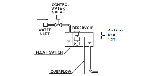
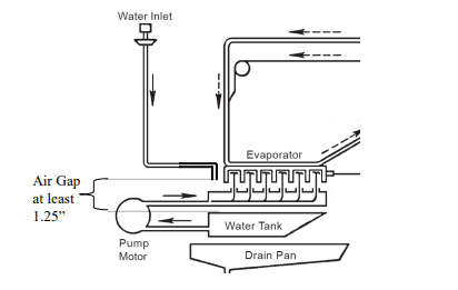
For the Flaker and DCM models, the water passes through the solenoid water inlet valve and through a 3/8” ID plastic fitting attached to the water valve outlet. The water then falls through the air into the water reservoir through a small hole. There is an overflow pipe in the reservoir that is 1 1/4 inches below the hole that the water enters through. The overflow pipe is connected to an open drain pan, therefore no water can siphoned back to the potable water supply.
AM-Models
For the AM models, water passes through the solenoid water inlet valve, it exits through a plastic tube that is vertically oriented and is held in position by a clamp attached to the icemaker wall. After exiting the tube, the water passes through a vertical air gap of more than 1.0 inch before it drops into the water tank. So even if some malfunction causes the water tank to overflow, the water will drop into the ice bin below it, and cannot reenter the vertically oriented water supply tubing above the water tank.
In all of our ice maker models, the built in air gap described above are secondary back up to the water solenoid valve. The water solenoid valves are normally closed and in most situations prevent any back siphonage from happening.
KM Cuber FAQs
When the machine beeps once every 3 seconds it indicates the HIGH TEMPERATURE SAFETY switch has been triggered.
The HIGH TEMPERATURE SAFETY is activated, when the thermistor which is mounted on the suction line reaches a temperature of 127° F. When this occurs it will shut the unit down, trigger the alarm, and lock it out on a manual reset safety.
Some of the reasons for a High Temperature safety alarm are as follows. You will find these possibilities included on the control board diagnostic label located in the compressor compartment. Follow the instructions provided on the label to reset the alarm and check these areas to locate the problem.
- Check to see if there is a mechanical problem with the hot gas valve sticking open or with the control board relay sticking.
- Check for a temperature differential across the hot gas valve.
- To check for a sticking relay, use a volt meter to check for voltage on pink wire, pin # 2 on the K1 connector.
- Hot water migration can also cause this. This typically happens at night when the only piece of equipment requiring water flow is the ice machine.
- Hot water migration is a tough problem to find and to prove to the customer. The best way to determine that this is happening is to place a temperature recorder on the inlet water line of the ice machine. The recorder will show when migration occurs.
- Usually hot water migration is due to a defective mixing valve in the existing plumbing. A good place to check is the pre-wash area at the dishwasher.
- A stuck head master on a remote air cooled condenser unit operating in a high ambient condition.
- The best way to check for this is to carefully touch the liquid line connection at the rear of the unit. Also, check for heat at the inlet pipe to the receiver tank. If these areas are hot, the head master is likely stuck in the bypass mode.
- Check for a shorted thermistor. If the thermistor reads approximately 500 ohms or less the control board will lock out on this safety.
- A shorted thermistor will signal zero ohms and cause repeated shut down on HIGH TEMPERATURE SAFETY.
In this article (video tutorial also available) we are going to cover the details of thoroughly cleaning a Hoshizaki ice machine. We find a great deal of warranty claims being submitted for parts that have failed due to lime or calcium scale build up. This is a result of machines not being cleaned at all or not being cleaned thoroughly. The cleaning instructions are posted on the inside of the front panel of the unit, in the instruction manual provided with the unit generic instructions can be found in our Pocket Guide.
Hoshizaki recommends that the machine is cleaned and sanitized at least once a year. In areas where water is undesirable, more cleaning will be required and external water treatment may be necessary.
The first thing you need to do is remove all the ice from the bin. This will prevent any of the cleaning solution from contaminating the ice. Next, turn the water off and drain the water sump tank. Depending on the model of the unit there are several ways to accomplish this. On most small KM’s, there is a drain or suction hose that you can pull off and let the water drain inside the bin. In some models the overflow pipe can also be removed to allow the sump to drain, turning the pipe counter-clockwise will allow it to be removed. On the stackable KM’s, there is a plug in the middle of the ice drop zone, toward the front of the unit, which can be removed to empty the sump. KML units have an automatic drain switch, which will allow the technician to simply use the units water pump to drain the sump. A drain plug is also included on the KML models so that the entire reservoir can be drained.
Now you’re ready to clean the Evaporator. Because, of Hoshizaki’s unique stainless steel evaporator any commercial ice machine cleaner can be used, a nickel safe type cleaner is not required. Hoshizaki recommends LIME-A-AWAY or Hoshizaki Scale Away which is available through your local distributor. Mix you’re cleaning solution with warm water in a bucket, follow the instructions on the rear of the front panel for the correct mixture ratio. Pour the solution inside the sump and move the toggle switch to the wash position. The KM units also have an additional cleaning valve that should be moved to the open or clean position. This will allow the cleaning solution to flow in between the evaporator plates as well as over the ice making side of the plate. It normally is only necessary to leave this valve open for about 5 minutes at the beginning of the cleaning cycle. It is important to return the valve to the closed position for the unit to make ice, the compressor will not operate unless this valve is completely closed. The KML units will not have the manually operated cleaning valve, instead it has a solenoid valve that automatically energizes when the second toggle switch is moved to the wash position. The KML units have two toggle switches, one is marked (Service, Off, and Ice) and the other (Drain, Circulate, and Wash.) The first switch, when placed in the Service position, will allow you to disengage the compressor and engage the second toggle switch. With this switch you can drain the unit or circulate the cleaning solution.
The solution should be circulated until the unit is clean. This may require a substantial amount of time depending on how dirty the unit is. There may be times that a more thorough cleaning may be required. This may be necessary when units are in bad water conditions or when the units have not been maintained correctly. There are a couple of ideas that may help in these tougher situations. The first is to move the spray tubes out about 1/2” this will allow the cleaning solution to run down the fins of the evaporator and assist in the cleaning Hoshizaki also has an evaporator brush (Part number 900019) that can be ordered through you’re local Distributor. This brush is a hard nylon bristle brush and fits tightly down the channels on the evaporator. This can be beneficial in removing scale that is the result of years of poor or no maintenance.
Now empty the sump by one of the methods mentioned above. With the sump empty remove the check valve, spray tube and float switch along with the rubber connector. These components should be taken apart and soaked in ice machine cleaner to allow the acid to break down any particle build up. While these components are soaking, remove the inlet water valve strainer and clean it. It is also a good idea to take the water valve apart and insure that the diaphragm is free of scale and the diaphragm’s weep hole is clear.
Now that your ice machine is clean the unit should be sanitized. The de-scaling chemicals will not clear the algae and bacteria that can develop on the ice machine. You should run the sanitizing chemical through the unit in the same manner that the cleaner was circulated. Be sure that the cleaner and sanitizer are not mixed. Doing so could be harmful.
Remember maintaining your customers unit will increase the life of the machine and decrease service calls. It is the responsibility of the owner to maintain his or her equipment properly. Components that have failed due to scale build up or a lack of preventative maintenance are not considered warranty issues
First, let me say that 9 out of 10 callbacks on a new unit are related to the machine not being installed according to the factory specs. This problem is no exception. When we receive calls about this problem the solution usually lies in the external drain circuit. When installing a Hoshizaki ice machine, the technician should refer to the Instruction Manual that comes with the machine. You can also find information on installation in the Hoshizaki Technician’s Pocket Guide.
All Hoshizaki icemakers require a dedicated ¾” ID drain for the reservoir. This can be plumbed using either copper or PVC. On KM’s that use water cooled condensers, the outlet of the condenser should be ½” and piped separately from the sump drain. On all Hoshizaki KM units manufactured after 1988, the unit will start in the one-minute fill cycle. Within 60 to 90 seconds you should see water coming from the sump drain. This will assure us that the unit has good water volume to the machine. During the harvest cycle the water valve will remain open. This water is used to flush the bottom portion of the sump. The water coming in will help agitate the minerals that lie at the bottom of the sump tank and flush them down the drain.
Now we will address the problem, because of the flushing action in the harvest cycle, it’s important that the reservoir drain not be smaller than the required ¾”. The drain should also be vented; this is typically done using a tee at the back of the unit. The unit drain should never be tied in with the bin drain. Proper plumping practices should be followed when running the drain line to the floor drain.
The two items that most often cause this problem are:
- The sump drain is too small, or
- there is a restriction in the external drain circuit.
To find out where the restriction lies, cut the drain about 12” below the vent tee and place a 5-gallon bucket to catch the water during the harvest cycle. If the water stops overflowing inside the bin, the restriction is further down the external drain system. If the problem still occurs, then the restriction may be in the machine, between the standpipe and the drain outlet. Slime or other build up normally causes this type of restriction in the drain. You can usually blow nitrogen or CO2 through the drain to clear the restriction. If this restriction is found to be slime or algae build up the entire machine should be cleaned and sanitized. I hope that these suggestions will help you solve the problem of the reservoir overfilling and water falling into the bin.
In this article we will assist technicians in troubleshooting the 3 beep error code. The 3-beep error is the result of two consecutive long freeze cycles. The length of the maximum freeze cycle is determined by the position of DIP switches 9 & 10. Settings for these DIP switches are shown below.
| DIP SW. 9 |
DIP SW. 10 |
MAX. FREEZE TIME |
| ON | ON | 75Min/50hz 60Min/60hz |
| ON | OFF | 70Min |
| OFF | ON | 50Min |
| OFF | OFF | 60Min |
When the freeze cycle has reached the maximum freeze time and the float switch has not opened to terminate the freeze cycle the control board will automatically initiate a harvest cycle. After completion of harvest the unit will continue into the next freeze cycle. If the next freeze cycle reaches the maximum freeze time the back up timer will again initiate the harvest cycle. This is when the safety alarm engages and locks the machine out on a manual reset, 3-beep audible alarm.
The freeze cycle on Hoshizaki KM ice machines is controlled by water level. As the ice is being formed on the evaporator the level of water in the reservoir drops. Once it has dropped low enough to open the float switch the freeze cycle is terminated and the pump out or harvest cycle begins. During normal operation the water level must drop before the unit will go into harvest. In the case of the 3-beep alarm, the harvest cycle was not initiated by the float switch opening.
Before beginning our troubleshooting, we must reset the control board. On the control board next to the yellow and orange LED there is small alarm reset button. Press and release this pin while the board is beeping. Pressing this pin with the power off will not reset the alarm. Once reset we can troubleshoot the three-beep error.
Many times the reason for erratic operation is caused by a dirty or scaled machine. Before beginning your troubleshooting please make sure the machine has been thoroughly cleaned. Evaporators, water valve, float switch all need to be cleaned before proceeding into the trouble-shooting phase.
For more detailed information on cleaning, see Tech Tip Vol. 186. Now that the machine and float switch are clean, we need to confirm component operation. Since the float switch actually sends the unit into harvest, it will be first on the list.
Float Switch: To check the float, remove it from the machine and check the continuity of the switch. Remove the float switch plug from the K5 connector on the board. With your ohmmeter on the plug wires and the float in the down position the switch is open, when it is up or the float turned upside down, the switch is closed. If the switch is closed or open all the time, no matter what position the float is in, the float switch needs replacing. The number one cause for failure of float switches is
scale.
Water Inlet Valve: This valve should be completely closed during our freeze cycle. To check this part pull the small hose off the water valve outlet going to the evaporator section. No water should be flowing from this valve during the freeze cycle. If water is by passing the valve, disassemble and clean/replace if necessary. See SB01-0009 for more info on water valve rebuilding.
Control Board: Test the control board, float switch operation. After 5 minutes of freeze drain the water out of the reservoir. When the water has drained the float switch will open and the control board will terminate the freeze cycle and initiate the harvest or pump out cycle. If the freeze cycle does not terminate, remove the K5 connection to the board. If the unit still does not go into harvest, the control board is defective.
IT IS IMPORTANT TO CONFIRM WHAT PORTION OF THE CYCLE THE BOARD IS IN. WITH “E” STYLE CONTROL BOARDS THIS CAN BE DONE BY CONFIRMING WHICH LED LIGHTS ARE ENERGIZED. WHEN THE BOARD IS IN HARVEST, LED 1, 4 AND 2 SHOULD BE ENERGIZED. WHEN THE CONTROL BOARD GOES INTO THE FREEZE CYCLE LED 1 WILL ENERGIZE. IF YOU ARE WORKING ON A UNIT WITH AN EARLIER CONTROL BOARD THIS CHECK CAN BE DONE USING A VOLT METER. WHEN THE UNIT IS IN HARVEST YOU WILL READ 115 VAC AT THE PINK WIRE AND WHEN IT IS IN FREEZE THE BLACK AND RED WIRES WILL BE ENERGIZED.
Water Pump: The water pump itself can be easily tested by putting the unit in wash. We must however also confirm the operation of the water pump in conjunction with the control board. When the unit begins the freeze cycle, the water pump and condenser fan motor should energize on self-contained units. (Remote units the condenser fan starts with the compressor.) If the water pump fails to come on check voltage from the control board K1 connector, red wire, we should see 110 volts. If not, it is a good idea to verify that the board is actually in the “freeze” cycle. See note above to confirm cycle. If we find red with power at the control board and the pump is still not running, next check the toggle switch.
Toggle Switch: Here you will find two red wires. Without removing them from the toggle switch check each one to ground for 110 volts, if one has power and the other does not, the toggle switch contacts are open. If you temporarily jump these wires together, the pump should energize. If we find voltage on both, check voltage at the pump itself, we should read 110-115VAC between black and red at the Molex connector. If we have voltage there, the pump is suspect.
Hot Gas Valve (HGV): To check the hot gas valve allow the unit to run in the freeze cycle for five minutes. Next place a temperature sensor on the outlet side of the HGV (about 3 to 5 inches down stream from the valve body) we should be reading approximately ambient temperature. If the temperature is high, confirm the valve is not being energized by checking voltage from the pink wire on the K1 connector to neutral. If no power is present the valve body is stuck open mechanically and should be replaced. When replacing any Hot Gas Valve always replace the strainer as well, along with the system drier. If power was present on the pink wire the control board is defective or a rare possibility of a back feed voltage keeping the coil to energize. (Remember make sure the board is in the freeze cycle; see information under water pump).
After checking that the HGV is operating correctly, we will now look at the remaining refrigeration system. To continue the testing it will now be necessary to install your gauges and check for the high and low side pressures at five minutes into the freeze cycle. (Refer to the performance data pages in the Tech Spec pocket guide for proper refrigerant pressures). You will also need to know the ambient temperature at the condenser, water inlet supply temperature and compressor amperage.
If you find that the pressures are low on the suction and high side we recommend that you check for leaks. If a leak is found use proper refrigeration practice to repair the leak and weigh in the nameplate charge.
Head Master: If the headmaster has failed in the “by-pass” mode you will find the liquid line and the discharge line close to the same temperature and at the same time, the head pressure is well above the headmaster setting. This causes discharge gas to be directed to the receiver tank instead of being routed through the condenser. This may cause the unit to cycle on the high pressure switch. Also, in some cases the discharge bypass will result in long freeze cycles or possibly a (1 beep) high evaporator temperature safety shutdown. The liquid line temperatures should be ambient plus 10 to 20°F. (See Tech Tip 206 for detailed information on Headmaster troubleshooting and the Tech Spec guide for individual Headmaster settings).
With a Water Cooled machine, make sure that the head pressure is adjusted correctly by checking the condenser outlet water temperature this should be adjusted between 100 and 110°F, if not you should adjust the water regulating valve. (Note: Please refer to the individual Tech Spec. guide for actual setting for your model).
TXV: To test the expansion valve or valves, remove the remote sensing bulb from the suction line during the freeze cycle. Hold the sensing bulb or bulbs in your hand and watch the suction line pressure increase, when this pressure settles in, drop the bulb or bulbs into a glass of ice water. The suction pressure should start falling. Once it has “bottomed out”, check to see if the swing of the TXV(s) was more than 7 to 10 psig for R-404a units and 10 to 15 psig. If the suction pressure has less swing the TXV(s) would be suspect and should be replaced. If the swing is found acceptable we then look towards our compressor.
When checking the compressor, first look at the amp draw for the compressor at 5 minutes into the freeze cycle along with the refrigerant pressures. Compare these readings to the Performance data chart for that model (Found in the Tech Spec guide). If the amp draw and head pressure are found to be low and the suction pressure is high, an inefficient compressor is possible. It is a good idea to eliminate all other possibilities before considering the compressor as some of the symptoms are similar between a faulty HGV, TXV, low charge, etc.
Other possibilities are Liquid line solenoid valves and driers that are restricted. Restrictions in these components will typically cause frost during the freeze cycle. If completely restricted however, you may see extremely low suction pressure possibly even a vacuum condition.
Hopefully the information provided in this article will help you easily diagnose the cause of a 3 beep safety shutdown.
This situation can be caused by several reasons. First we must determine the presents of proper supply voltage and water supplied to the unit. Now that this is confirmed, let’s look at the possible problems.
The next item to check is the bin control. Do this by simply moving the toggle switch to the wash position , if the pump runs the bin control is closed. If the pump does not start, check the control with a volt-ohm meter for continuity. Please note that on older KM- DU, DWU, & DSU models, there is a 4 to 5 minute delay before the pump starts.
Now check the K1 connector. Begin with the brown wire #10 on Alpine boards and #1 on “C” board applications. First confirm 115-120 Volts from this point to ground or neutral. Since we have confirmed that the bin control is closed, power should be supplied at this point. If not, there is a problem with the wire or connection between the bin control and the K1 connector.
Now that power is established to the board on the brown wire, check for control voltage to operate the board. Locate the K2 connector and check across the two red wires for 10.5 to 12 volts AC. This voltage is supplied by the low voltage control transformer. If no control voltage is present, check to insure that the wash valve is closed and the handle is depressing the micro switch (interlock). Check for a closed micro switch with a volt meter. ( Note: On older “A or B” board units, the control transformer is mounted directly to the board. These boards do not have a K-2 connector. You can check the input and output voltage on back of the board to verify a bad control transformer. The control board must be replaced if this control transformer fails.)
Next check the primary of the control voltage transformer. On most models it will be the black and brown wires. If no primary voltage is present on the transformer you will need to trace the path of the primary voltage supply. Depending on the model, there could be a high pressure, low pressure, discharge temperature, and toggle switches in series in this circuit. If any of these are open, there will be no primary voltage on the control transformer and the unit will not start. The board will not allow start up without proper control voltage.
Having confirmed power to the brown wire on K-1 and proper control voltage on K-2, check for 115-120 volts at the orange wire #6. This wire supplies power to the inlet water valve circuit. If no power is present at this time , the control board is defective. If power is present, check across the orange and white wires on the water valve. With power at the water valve and no water is flowing, either the water valve is bad or the valve inlet screen is plugged. Turn off the water and check the screen. If it is not plugged replace thedefective water valve and check the unit for proper operation.
By following these steps you should be able to discover why the unit will not start or fill.
A longer harvest cycle in the winter is a common occurrence. Though the thermistor is a possibility since it is the component that begins defrost termination, let’s not be too quick to condemn it. First, let’s take a look at what happens to our harvest cycle under cold water conditions (45 degrees or less). Remember that we bring in all of ice making water during the harvest cycle. The inlet water passes through the middle of the evaporator plates. This allows us to achieve good even heat distribution across the entire evaporator surface. We call this system a hot-gas, water assisted harvest.
As mentioned earlier the thermistor is what begins defrost termination. The thermistor is mounted on the suction line where it is waiting to sense 48 degrees. At this point it will initiate the defrost completion timer on the control board. After the adjustable defrost timer times out, the unit will end harvest. The harvest however, will not end for a minimum of two minutes. The board controls this function. If we are bringing in water that is colder than our minimum spec, it will take longer to reach 48 degrees on the suction line. This gives us a longer harvest cycle in cold water situations. The use of the thermistor is one of the reasons that our machines do not require seasonal adjustments (See Tech tip 109).
The inlet water valve will only stay energized for 6 minutes during the harvest cycle. In cold water conditions, stopping the water flow will allow the heat to build in the evaporator and on the suction line. This allows us to reach our target temperature at the thermistor and start the defrost completion timer in the board. You will find that it is not abnormal to see an 8~10-minute harvest cycle when experiencing cold water conditions.
Now, let’s discuss what happens if you are having long harvest cycles regardless of the water temperature. It is important to keep in mind that our harvest cycle is temperature and time terminated. When you are having a problem with long harvest, the easiest way to troubleshoot the problem is to perform the “3 step check” (or at least that’s what I call it). Let’s take a minute and discuss these 3 steps.
- Turn off power to the machine and strap a good surface probe from your digital thermometer to the suction line. It should be as close as possible to the thermistor, without disturbing it’s mounting. Next unplug the thermistor from the white K3 connector on the board and turn the machine back on. Let the machine go through the one minute fill and cycle into the defrost mode. Watch your thermometer, if or when it reaches 50 degrees you have completed step 1. This determines that the defrost portion of your refrigeration cycle is working properly. If it does not reach 50 degrees then you have established that you have some type of refrigeration problem. You will want to look at items that would prevent you from heating your evaporator to 48 degrees such as low charge, hot gas valve not open, line valve leaking by (if it is applicable to your model) etc…
- Once you have reached 50 degrees ohm out your thermistor which should read 3.9 K ohms or less depending on how much above 50 degrees you are reading. (Refer to the “component checks” page of your Tech Spec for a temperature resistance chart). If you do have the correct reading, you have established that your thermistor is operating properly. If your thermistor reading is out of spec, the thermistor is either mounted incorrectly or is defective. Check the mounting first. It is very uncommon to have a thermistor fail in this manner. In the rare cases of a thermistor failure, it is typically either open or shorted.
- Once you have established that there are not any problems with the refrigeration cycle and the thermistor, then simply plug the thermistor back to the K3 connector and start timing. The machine should come out of harvest in a maximum of 3 minutes. It could come out in 60, 90, 120 or 180 seconds depending on the setting of dipswitches number 1 and 2. If the machine fails to end harvest in 3 minutes, you probably have a board problem.
Well there you have it, “the 3 step check”. Hopefully the next time you have a problem with defrost on a Hoshizaki KM cuber, these 3 steps will point you in the right direction for a correct diagnosis.
This is a common question asked by service technicians and is relatively easy to diagnose. First, remember that there are backup timers incorporated in the solid state control board. This includes a five minute short cycle protection timer and a sixty minute maximum freeze timer. The board has the freeze cycle under control for the first five minutes. This is the short cycle protection timer. After five minutes, the board waits for the float switch to open contacts. This occurs when the water level in the reservoir drops to a certain point. In order to determine what the freeze cycle should be running, check the reference material. This information is found in the Tech-Specs or individual service manuals. By referring to the production charts, determine approximately how long the freeze cycle should be. This time will be affected by ambient conditions and water temperature and should be used as a guideline.
If it has been determined that the freeze cycle is too long, there only a few things that could cause this. Here is a list of what to check:
FLOAT SWITCH: The float switch initiates the KM cuber harvest. If in 60 minutes, the float switch failed to open its contacts, the board will automatically put the unit into harvest. The symptoms of a stuck float switch is a consistent 60 minute freeze cycle. The cube will be larger than normal. Also the reservoir may run short of water before 60 minutes expires causing the pump to suck air. When the freeze cycle is started, the board starts the maximum freeze timer. If the contacts stick closed, this would cause a long freeze cycle. The float switch can be checked by using a simple ohm meter. If the float is in the up position, the switch is closed. If the float is down, the switch is open. The float switch could be dirty. Clean it and recheck the contacts. If the float switch is still reading closed when it should be open replace it.
WATER VALVE: Another cause of a long freeze cycle may be a leaking water valve. The water valve should shut completely off when de-energized. If it fails to do so, it will continually let water in the reservoir. This will lengthen the freeze cycle. The actual increase in cycle time will depend on how much water is seeping past the water valve diaphragm. If the water is flowing excessively, no ice will be made. In this case clean the bleed port in the valve diaphragm, replace the diaphragm, or replace the water valve. The symptoms would be up to a 60 minute freeze cycle if the valve was leaking excessive water into the reservoir.
CONTROL BOARD: The control board could cause a long freeze cycle. To check this disconnect the float switch from the board after five minutes in the freeze cycle. The machine should go directly into the harvest cycle. If this does not occur, the board should be replaced.
Each of these problems will produce an oversized cube. Long cycles can also be caused by a refrigeration problem. A long freeze cycle that produces a small cube or no cube at all will most likely be linked to a weak compressor, expansion valve, or some other refrigeration problem. Use basic refrigeration principals to diagnose these areas.
Cuber Production Check
Spring has sprung and hot weather is on the way. Higher temperatures outside means more ice usage inside. A properly sized unit will provide adequate capacity in these peak periods of use. However, this is not always the case.
In the peak summer time, ambient conditions and inlet water temperatures are at their highest and unfortunately, the ice machine output will be at its lowest. This usually results in a customer complaint if the unit was not sized properly for peak periods.
At this time the unit should be checked thoroughly for proper operation. Be sure to check that the evaporator, condenser, air filter, water filter and water valve are clean before conducting a production check. Also utilize the 10 minute checkout procedure to assure proper operation. The steps for a cuber production check are as follows:
- Time a complete cycle from the beginning of one freeze cycle to the beginning of the next freeze cycle.
- Catch all of the ice from this freeze cycle and weigh the total batch.
- Divide the total minutes in a 24 hour day (1440 minutes) by the complete cycle time in minutes to obtain the number of cycles per day.
- Multiply the number of cycles per day by the cycle batch weight for the cuber production per 24 hours.
Once you calculate the production, check the incoming water temperature, and ambient condensing temperature of the cuber and cross reference the Data Specification Chart in the unit Service Manual to see if the calculation falls within 10% of the specification. If not within specifications, additional trouble shooting is required to find out why.
For the most accurate production check, a normal freeze cycle should be checked. If the evaporator compartment has been opened for service or if the unit has been cut off for a long period of time, the first freeze cycle will be longer than normal. Timing this cycle can result in an inaccurate production check.
To avoid this, start the unit and allow it to operate for 10 minutes in the freeze cycle, unplug the float switch lead and cause the unit to cycle into harvest mode. Start timing as soon as the next freeze begins. Also remember that the evaporator compartment must be closed during the production check. Removing the front cover to check the ice buildup during a production check will allow heat into the evaporator and will effect the total cycle time and actual production.
A complete inspection and production check on a KM Cuber can easily be completed in approximately 1 hour. This is an effective tool to help you prove to the customer that the unit is indeed performing according to specifications.
Small cubes on a KM cuber mean only one thing. There’s not enough water to make normal size cubes or the water is disappearing. During harvest, the reservoir should fill to overflowing. If it does, there is plenty of water in the reservoir for a full batch of normal size KM cubes. If it doesn’t fill to overflowing check the incoming water supply. A plugged external filter or inlet water valve screen is likely. Low water pressure or an improper inlet water line size is also a possibility.
If the reservoir filled properly during harvest, the water had to go somewhere. In this case check for leak by at the pump-out check valve caused by dirt, scale, or a weak spring. Also look for a missing displacement cap or o-ring for the drain stand pipe. A water trail caused by shipping tape, an out of position ice chute guide, or algae can cause water to run into the bin. There is also the remote possibility of a leaking reservoir. Search until you find the missing water culprit and correct it, and the KM cube size should return to normal.
This is one of the most common questions asked Technical Support. Before we look at the possible causes we must understand two things.
- The first is that the KM series goes into harvest by water level, and not by temperature. This occurs as the water level drops and the float switch opens.
- The second is that the water level is controlled by the stand pipe in the reservoir and not by the float switch or control board. The reservoir of the KM series cuber fills with water one time during the ice making cycle. This occurs during the initial fill and harvest cycle only. The reservoir should fill and begin to over flow the stand pipe within about 90 seconds if proper water flow is available.
Now, we will look at the possible causes for a 5 minute freeze time. The first items to check are the float switch and control board operation. This is done by placing a jumper across the float switch connector and allowing the unit to sequence into the freeze cycle.
If the unit continues to sequence into the harvest cycle after 5 minutes, replace the board. If the unit remains in the freeze cycle, check the operation of the float and the following items. It is possible that the reservoir was not completely full at the beginning of the freeze cycle. This can be easily checked by watching the unit drain during the harvest cycle. Water should overflow the stand pipe and drain within the first 60 to 90 seconds of a normal harvest cycle.
If water does not overflow the drain, check for proper water line size and pressure. Also check for a plugged external filter system or inlet water valve screen, and check for proper operation of the water valve. If the reservoir fills properly, the next possibility is that the pump out check valve is stuck open. The easiest way to check for this problem is to see if you have water coming from the drain during the freeze cycle. This tells you that the check valve is stuck open, dirty, or has a weak spring. Disassemble the check valve housing and clean the valve seat. If the spring is weak, a temporary fix is to stretch it a little. This will get you by until you can replace it with a new one.
Checking these items should help you resolve a consistent 5 minute freeze cycle.
You will find that the main reason for a freeze up is either a dirty evaporator or low water flow. After de-frosting the evaporators check to see if the they are dirty (i.e.: lime-scale mineral deposits). Turn the machine on and after the compressor starts, shut off the incoming water and allow the plates to dry.
After an approximate run time of 2-4 minutes, switch the unit off and inspect the evaporator plates. You will find that salt from a water softener can form an invisible coating on the plates. Care should be taken to purge a water softener when charging it to eliminate this possibility. If scale or a salt coating is present, clean the water system with Hoshizaki Scale- Away as required. Follow the instructions provided on the cleaning label on the inside of the front cover of the machine.
Verify that the incoming water flow rate is 3GPM for KM 250-800 machines, 5GPM for KM-1200- 2400 machines. One technique to check this, is to time the fill cycle when the sump tank is empty and see if the tank overflows in 60 ~ 90 seconds or less. If you find the water flow is reduced, check the external water filters and replace as needed.
Inspect the water inlet solenoid valve and clean the inlet screen if necessary. Confirm that the water line size is of adequate size (3/8” o.d. for KM-250~800 models and 1/2” o.d. for KM-1200~2400 models).
After determining the water flow is OK, check the bin control by placing ice on the bulb. The machine should shut off in 6-10 seconds. If not, adjust it for proper operation or replace it as needed. If your machine is a an “S” model installed on a non- Hoshizaki bin, make sure you have a bin extension bracket installed. Hoshizaki part number 3A0408-01 is an additional stainless steel extension bracket that is to be attached to the existing white A.B.S. plastic bulb bracket. This bracket lowers the ice level inside the bin to where the last ice drop is able to clear the chute area into the bin, eliminating ice back-up.
Other areas to check are, is the ice still dropping into the bin when the unit cycles into the freeze mode? If so check for cold incoming water temp or low hot gas flow. Does the inlet water solenoid valve close completely during the freeze cycle? If not check the water valve diaphragm and clean or replace diaphragm or valve as needed. Further testing could include checking the hot gas valve inlet and outlet temperature during harvest making sure the valve is functioning. Also inspect the water pump to be sure it is always running during the complete freeze cycle. Make sure the float switch is operating correctly and that it is clean. We have a freeze-up check list available, if you need one or have any questions contact the Technical Department.
Our old friend Barney Fife, would take a great big ax or ice pick, and go POW, POW, POW. We have even seen situations where a hammer and screwdriver were used. Obviously these are not good methods to thaw an evaporator. Though they can be effective in removing ice, these methods usually result in serious damage to the evaporator and loss of refrigerant.
Now that we have talked about ways not to clear a freeze up, lets look at a couple of less destructive ways to accomplish this task.
The best method will depend on what you have at your disposal. One of the best ways is if you have access to a hot water supply. You will find a mop sink is an excellent source for hot water. Attach a hose to the water supply and run water directly into the reservoir. You can then put the machine in the wash position and let the pump run. It will be necessary to adjust the flow of water coming into the sump so as not to overflow hot water into the bin. The constant flow of hot water in the sump will insure that the sump stays full of water as well as preventing the sump water from becoming chilled. Using this method you may be able to run another service call while the machine is being defrosted.
You can also remove the ice by just spraying hot water directly onto the frozen portions of the evaporator. This method requires that you remain in front of the machine the entire time, but usually is a little quicker since you can spray the water directly to the areas needed.
You can also turn the machine into wash and let the pump re-circulate water over the frozen evaporator. I would not recommend this however, if you plan to leave the location. There are a couple of concerns. The worst problem could be that the sump tank could run dry due to water being diverted into the bin by the ice build up. This could result in damage to the pump. You will also find that the water will become extremely cold, reducing the effectiveness.
Be careful when using any of these methods to prevent large chunks of ice from falling on and damaging the cube guides. As you know our machine starts in the harvest cycle. I have seen technicians turning the machine on and off to try and clear the ice. We do not recommend that the unit be continually recycled to try and clear the ice. This method is not as effective as the others, and could cause problems with the compressor.
The most important thing, now that the ice is thawed, is to find the cause of the freeze up. You can learn more about freeze ups in previous volumes of the Tech Tips 103 and 128. You will also find useful information including a freeze up checklist under “Diagnosing water problems” in the Tech Specs. Following the checklist will help you pinpoint the cause of most freeze-up problems.
When diagnosing an ice machine, there are many obvious symptoms that will point you in the right direction. One such symptom can be found by inspecting ice in the bin. Odd shaped ice cubes generally point to water related problems. By inspecting the shape of the cubes, you can know which area to check first.
Here’s an example: A customer calls to complain of running out of ice (low production). Upon arriving at the site, you question the owner and find that the ice drops about once an hour. The owner also mentions that the cubes appear bigger than normal. Looking in the bin, you find larger than normal or huge cubes. These cubes are thicker and taller than they should be and may roll up on the edges.
You remember that KM series control boards styles B, C, and Alpine have a 60 minute back-up freeze protection timer. This timer will automatically switch the unit to harvest, if the float switch does not open within 60 minutes. A 60 minute freeze time will utilize all the water in the reservoir to make ice and possibly cause the pump to suck air or cavitate (form bubbles) towards the end of the cycle. Adding two and two together, 60 minute cycles plus huge cubes equals a float switch stuck in the up or closed position. Likely, the float switch is sticking due to scale build-up. You should clean the float switch with ice machine cleaner and check the operation with a quality ohm meter. Simply replace a float switch that doesn’t check properly after you clean it.
There is another rare possibility in this case. This should be checked after you eliminate the float switch. Check to see if the inlet water valve leaks a little additional water into the reservoir. Just enough to cause a 60 minute cycle and huge cubes. You will find that in most cases, if a water valve leaks, it adds so much water to the reservoir that the ice bridges together on the entire evaporator. If the water valve is stuck wide open, the reservoir water temperature is tempered so much by the incoming water that no ice is produced. You will detect either ice bridging or a fully open water valve immediately.
Huge cubes will generally harvest properly unless combined with a dirty evaporator or low water flow. If all cubes do not fall during harvest, a freeze-up could occur. In this case a thorough preventative maintenance cleaning and external filter check should be completed.
Recently there have been several inquiries concerning the provision in our icemakers to prevent back flow from the icemaker into the potable water supply. If there is not a provision to prevent this, during a period of negative pressure of the potable water supply, water from within the icemaker could be siphoned back into the potable water supply, causing contamination.
All of our KM series units (Including KML, KMS, KMD, etc.), Flaker, DCM, and AM model icemakers are listed by NSF International under NSF Standard 12, Automatic Ice Making Equipment.
As part of getting listed by NSF, an icemaker must comply with section 5.28 “Backflow Prevention” of NSF 12. Section 5.28.1 states “Units intended to be connected to a water supply system under pressure shall have one of the following:
“-an air gap at least twice the diameter of the water supply inlet and not less than 1.0 in (25 mm): Or”
This clause goes on to state several other methods of meeting this requirement however, the first method is how all of our models meet the requirements.
KM-Models
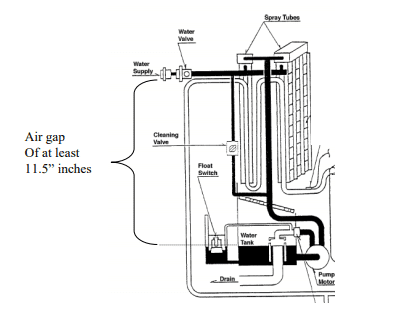
For the KM models, the water passes through the solenoid water inlet valve to the top of the KM evaporator plates. The water falls by gravity between the evaporator plates and over the refrigerant tubing sandwiched between them. It then falls further through the cube guide and into the reservoir tank. The space between the two stainless steel plates is open to atmosphere, so once the water leaves the water spray tubes, it is in an air gap the height of the evaporator plates. The height of the KM evaporator plates is minimum 11.5 inches, which easily meets the NSF requirement.
Flaker and DCM-Models
For the Flaker and DCM models, the water passes through the solenoid water inlet valve and through a 3/8” ID plastic fitting attached to the water valve outlet. The water then falls through the air into the water reservoir through a small hole. There is an overflow pipe in the reservoir that is 1 1/4 inches
below the hole that the water enters through. The overflow pipe is connected to an open drain pan, therefore no water can siphoned back to the potable water supply.
AM-Models
For the AM models, water passes through the solenoid water inlet valve, it exits through a plastic tube that is vertically oriented and is held in position by a clamp attached to the icemaker wall. After exiting the tube, the water passes through a vertical air gap of more than 1.0 inch before it drops into the water tank. So even if some malfunction causes the water tank to overflow, the water will drop into the ice bin below it, and cannot reenter the vertically oriented water supply tubing above the water tank.
In all of our ice maker models, the built in air gap described above are secondary back up to the water solenoid valve. The water solenoid valves are normally closed and in most situations prevent any back siphonage from happening.
Technical FAQs
For information on how to submit a Hoshizaki warranty claim, visit the Warranty page.
When restarting an icemaker after a period of non-use, first clean and sanitize the icemaker as outlined in the Cleaning and Sanitizing Instructions section of the appliance’s instruction manual.
Yes, but then you will need to chalk around the base of ice maker. Most state/county/local health code requires 6″ space under equipment in order to clean. If you remove the legs, then these codes specify chaulking all along the base to prevent spills and dirt from getting under the machine. Please note if you do not use legs: If you need to pull out the icemaker to service and/or maintain – then you will need to reapply fresh chaulking.
No. LP-4=LEG has a 3/8-11 thread. Uprights can accommodate 5/8-11 threads. In addition, 4″ legs may not be allowable since NSF requires anything under 6″ must be sealed to the floor unless the unit is on casters.
Steelheart upright models can accommodate optional 6″ legs. LP-6-LEG, LP-6P-LEG or LP-6 FLANGE LEG
Visit Energy Star Models
Shelf weight capacities are listed in our instruction manuals.
Do not throw anything on the shelves or load a single shelf with more than 120 lbs. of product.
Since the 2 faucet tower comes with other models, it is available as a service part.
They can order a 2 faucet tower and replace the 1 faucet tower that comes standard.
12191241
Since the 1 faucet tower comes standard, it is available as a service part.
They can order a 1 faucet tower and replace the 2 faucet tower that comes standard.
12191240
Rear Mount models use 1/2-13 x 1.5″ long caster stems.
When the machine beeps once every 3 seconds it indicates the HIGH TEMPERATURE SAFETY switch has been triggered.
The HIGH TEMPERATURE SAFETY is activated, when the thermistor which is mounted on the suction line reaches a temperature of 127° F. When this occurs it will shut the unit down, trigger the alarm, and lock it out on a manual reset safety.
Some of the reasons for a High Temperature safety alarm are as follows. You will find these possibilities included on the control board diagnostic label located in the compressor compartment. Follow the instructions provided on the label to reset the alarm and check these areas to locate the problem.
- Check to see if there is a mechanical problem with the hot gas valve sticking open or with the control board relay sticking.
- Check for a temperature differential across the hot gas valve.
- To check for a sticking relay, use a volt meter to check for voltage on pink wire, pin # 2 on the K1 connector.
- Hot water migration can also cause this. This typically happens at night when the only piece of equipment requiring water flow is the ice machine.
- Hot water migration is a tough problem to find and to prove to the customer. The best way to determine that this is happening is to place a temperature recorder on the inlet water line of the ice machine. The recorder will show when migration occurs.
- Usually hot water migration is due to a defective mixing valve in the existing plumbing. A good place to check is the pre-wash area at the dishwasher.
- A stuck head master on a remote air cooled condenser unit operating in a high ambient condition.
- The best way to check for this is to carefully touch the liquid line connection at the rear of the unit. Also, check for heat at the inlet pipe to the receiver tank. If these areas are hot, the head master is likely stuck in the bypass mode.
- Check for a shorted thermistor. If the thermistor reads approximately 500 ohms or less the control board will lock out on this safety.
- A shorted thermistor will signal zero ohms and cause repeated shut down on HIGH TEMPERATURE SAFETY.
This is a common question and there are more factors involved than you might think. Many things have to be taken into consideration when designing an ice machine. Let’s take a look at some of those factors when considering the charge.
Once the components are selected, the first thing that is taken into consideration is selecting the type of refrigerant needed to match the system requirements and designed production. Other considerations include proper sub-cooling, superheat, evaporator and condenser temperatures, refrigerant pressures, etc. We must also take into consideration the compressor manufactures specifications. We must not exceed the manufacturer’s limits for dome temperature, discharge pressure, amp draw under maximum load etc. Finally, the machine is monitored cycle after cycle to insure consistent and maximum performance. As you see there are many variables that are looked at before deciding on the correct factory charge. This is what makes an ice machine a critically charged unit.
Because of the many factors involved in correctly charging any refrigeration system and a constantly changing load on the evaporator during the freeze cycle, it may be normal to have bubbles in a sight glass with a correctly charged unit. When charging, if you clear the sight glass of bubbles, you may have inadvertently overcharged the system. Therefore, our only recommendation for properly charging any of our models is by weighing in the correct charge according to the nameplate. If you do encounter a Hoshizaki machine with a sight glass it should only be used as a moisture indicator and not to charge the machine.
In this article we will assist technicians in troubleshooting the 3 beep error code. The 3-beep error is the result of two consecutive long freeze cycles. The length of the maximum freeze cycle is determined by the position of DIP switches 9 & 10. Settings for these DIP switches are shown below.
| DIP SW. 9 |
DIP SW. 10 |
MAX. FREEZE TIME |
| ON | ON | 75Min/50hz 60Min/60hz |
| ON | OFF | 70Min |
| OFF | ON | 50Min |
| OFF | OFF | 60Min |
When the freeze cycle has reached the maximum freeze time and the float switch has not opened to terminate the freeze cycle the control board will automatically initiate a harvest cycle. After completion of harvest the unit will continue into the next freeze cycle. If the next freeze cycle reaches the maximum freeze time the back up timer will again initiate the harvest cycle. This is when the safety alarm engages and locks the machine out on a manual reset, 3-beep audible alarm.
The freeze cycle on Hoshizaki KM ice machines is controlled by water level. As the ice is being formed on the evaporator the level of water in the reservoir drops. Once it has dropped low enough to open the float switch the freeze cycle is terminated and the pump out or harvest cycle begins. During normal operation the water level must drop before the unit will go into harvest. In the case of the 3-beep alarm, the harvest cycle was not initiated by the float switch opening.
Before beginning our troubleshooting, we must reset the control board. On the control board next to the yellow and orange LED there is small alarm reset button. Press and release this pin while the board is beeping. Pressing this pin with the power off will not reset the alarm. Once reset we can troubleshoot the three-beep error.
Many times the reason for erratic operation is caused by a dirty or scaled machine. Before beginning your troubleshooting please make sure the machine has been thoroughly cleaned. Evaporators, water valve, float switch all need to be cleaned before proceeding into the trouble-shooting phase.
For more detailed information on cleaning, see Tech Tip Vol. 186. Now that the machine and float switch are clean, we need to confirm component operation. Since the float switch actually sends the unit into harvest, it will be first on the list.
Float Switch: To check the float, remove it from the machine and check the continuity of the switch. Remove the float switch plug from the K5 connector on the board. With your ohmmeter on the plug wires and the float in the down position the switch is open, when it is up or the float turned upside down, the switch is closed. If the switch is closed or open all the time, no matter what position the float is in, the float switch needs replacing. The number one cause for failure of float switches is
scale.
Water Inlet Valve: This valve should be completely closed during our freeze cycle. To check this part pull the small hose off the water valve outlet going to the evaporator section. No water should be flowing from this valve during the freeze cycle. If water is by passing the valve, disassemble and clean/replace if necessary. See SB01-0009 for more info on water valve rebuilding.
Control Board: Test the control board, float switch operation. After 5 minutes of freeze drain the water out of the reservoir. When the water has drained the float switch will open and the control board will terminate the freeze cycle and initiate the harvest or pump out cycle. If the freeze cycle does not terminate, remove the K5 connection to the board. If the unit still does not go into harvest, the control board is defective.
IT IS IMPORTANT TO CONFIRM WHAT PORTION OF THE CYCLE THE BOARD IS IN. WITH “E” STYLE CONTROL BOARDS THIS CAN BE DONE BY CONFIRMING WHICH LED LIGHTS ARE ENERGIZED. WHEN THE BOARD IS IN HARVEST, LED 1, 4 AND 2 SHOULD BE ENERGIZED. WHEN THE CONTROL BOARD GOES INTO THE FREEZE CYCLE LED 1 WILL ENERGIZE. IF YOU ARE WORKING ON A UNIT WITH AN EARLIER CONTROL BOARD THIS CHECK CAN BE DONE USING A VOLT METER. WHEN THE UNIT IS IN HARVEST YOU WILL READ 115 VAC AT THE PINK WIRE AND WHEN IT IS IN FREEZE THE BLACK AND RED WIRES WILL BE ENERGIZED.
Water Pump: The water pump itself can be easily tested by putting the unit in wash. We must however also confirm the operation of the water pump in conjunction with the control board. When the unit begins the freeze cycle, the water pump and condenser fan motor should energize on self-contained units. (Remote units the condenser fan starts with the compressor.) If the water pump fails to come on check voltage from the control board K1 connector, red wire, we should see 110 volts. If not, it is a good idea to verify that the board is actually in the “freeze” cycle. See note above to confirm cycle. If we find red with power at the control board and the pump is still not running, next check the toggle switch.
Toggle Switch: Here you will find two red wires. Without removing them from the toggle switch check each one to ground for 110 volts, if one has power and the other does not, the toggle switch contacts are open. If you temporarily jump these wires together, the pump should energize. If we find voltage on both, check voltage at the pump itself, we should read 110-115VAC between black and red at the Molex connector. If we have voltage there, the pump is suspect.
Hot Gas Valve (HGV): To check the hot gas valve allow the unit to run in the freeze cycle for five minutes. Next place a temperature sensor on the outlet side of the HGV (about 3 to 5 inches down stream from the valve body) we should be reading approximately ambient temperature. If the temperature is high, confirm the valve is not being energized by checking voltage from the pink wire on the K1 connector to neutral. If no power is present the valve body is stuck open mechanically and should be replaced. When replacing any Hot Gas Valve always replace the strainer as well, along with the system drier. If power was present on the pink wire the control board is defective or a rare possibility of a back feed voltage keeping the coil to energize. (Remember make sure the board is in the freeze cycle; see information under water pump).
After checking that the HGV is operating correctly, we will now look at the remaining refrigeration system. To continue the testing it will now be necessary to install your gauges and check for the high and low side pressures at five minutes into the freeze cycle. (Refer to the performance data pages in the Tech Spec pocket guide for proper refrigerant pressures). You will also need to know the ambient temperature at the condenser, water inlet supply temperature and compressor amperage.
If you find that the pressures are low on the suction and high side we recommend that you check for leaks. If a leak is found use proper refrigeration practice to repair the leak and weigh in the nameplate charge.
Head Master: If the headmaster has failed in the “by-pass” mode you will find the liquid line and the discharge line close to the same temperature and at the same time, the head pressure is well above the headmaster setting. This causes discharge gas to be directed to the receiver tank instead of being routed through the condenser. This may cause the unit to cycle on the high pressure switch. Also, in some cases the discharge bypass will result in long freeze cycles or possibly a (1 beep) high evaporator temperature safety shutdown. The liquid line temperatures should be ambient plus 10 to 20°F. (See Tech Tip 206 for detailed information on Headmaster troubleshooting and the Tech Spec guide for individual Headmaster settings).
With a Water Cooled machine, make sure that the head pressure is adjusted correctly by checking the condenser outlet water temperature this should be adjusted between 100 and 110°F, if not you should adjust the water regulating valve. (Note: Please refer to the individual Tech Spec. guide for actual setting for your model).
TXV: To test the expansion valve or valves, remove the remote sensing bulb from the suction line during the freeze cycle. Hold the sensing bulb or bulbs in your hand and watch the suction line pressure increase, when this pressure settles in, drop the bulb or bulbs into a glass of ice water. The suction pressure should start falling. Once it has “bottomed out”, check to see if the swing of the TXV(s) was more than 7 to 10 psig for R-404a units and 10 to 15 psig. If the suction pressure has less swing the TXV(s) would be suspect and should be replaced. If the swing is found acceptable we then look towards our compressor.
When checking the compressor, first look at the amp draw for the compressor at 5 minutes into the freeze cycle along with the refrigerant pressures. Compare these readings to the Performance data chart for that model (Found in the Tech Spec guide). If the amp draw and head pressure are found to be low and the suction pressure is high, an inefficient compressor is possible. It is a good idea to eliminate all other possibilities before considering the compressor as some of the symptoms are similar between a faulty HGV, TXV, low charge, etc.
Other possibilities are Liquid line solenoid valves and driers that are restricted. Restrictions in these components will typically cause frost during the freeze cycle. If completely restricted however, you may see extremely low suction pressure possibly even a vacuum condition.
Hopefully the information provided in this article will help you easily diagnose the cause of a 3 beep safety shutdown.
Recently there have been several inquiries concerning the provision in our icemakers to prevent back flow from the icemaker into the potable water supply. If there is not a provision to prevent this, during a period of negative pressure of the potable water supply, water from within the icemaker could be siphoned back into the potable water supply, causing contamination.
All of our KM series units (Including KML, KMS, KMD, etc.), Flaker, DCM, and AM model icemakers are listed by NSF International under NSF Standard 12, Automatic Ice Making Equipment.
As part of getting listed by NSF, an icemaker must comply with section 5.28 “Backflow Prevention” of NSF 12. Section 5.28.1 states “Units intended to be connected to a water supply system under pressure shall have one of the following:
“-an air gap at least twice the diameter of the water supply inlet and not less than 1.0 in (25 mm): Or”
This clause goes on to state several other methods of meeting this requirement however, the first method is how all of our models meet the requirements.
KM-Models
For the KM models, the water passes through the solenoid water inlet valve to the top of the KM evaporator plates. The water falls by gravity between the evaporator plates and over the refrigerant tubing sandwiched between them. It then falls further through the cube guide and into the reservoir tank. The space between the two stainless steel plates is open to atmosphere, so once the water leaves the water spray tubes, it is in an air gap the height of the evaporator plates. The height of the KM evaporator plates is minimum 11.5 inches, which easily meets the NSF requirement.
Flaker and DCM-Models
For the Flaker and DCM models, the water passes through the solenoid water inlet valve and through a 3/8” ID plastic fitting attached to the water valve outlet. The water then falls through the air into the water reservoir through a small hole. There is an overflow pipe in the reservoir that is 1 1/4 inches
below the hole that the water enters through. The overflow pipe is connected to an open drain pan, therefore no water can siphoned back to the potable water supply.
AM-Models
For the AM models, water passes through the solenoid water inlet valve, it exits through a plastic tube that is vertically oriented and is held in position by a clamp attached to the icemaker wall. After exiting the tube, the water passes through a vertical air gap of more than 1.0 inch before it drops into the water tank. So even if some malfunction causes the water tank to overflow, the water will drop into the ice bin below it, and cannot reenter the vertically oriented water supply tubing above the water tank.
In all of our ice maker models, the built in air gap described above are secondary back up to the water solenoid valve. The water solenoid valves are normally closed and in most situations prevent any back siphonage from happening.
Ready for the Best in Ice and Refrigeration?
Discover how Hoshizaki products can meet the unique
demands of your business.